Download Catalog (PDF)
Download Specs Only (PDF)
Flat Oval Spiral Product Pages
 Flat Oval Spiral Pipe & Fittings
Sheet Metal Connectors, Inc. flat oval single wall duct and fittings are one part of our complete line of HVAC products. Flat oval duct has been designed for restricted space conditions that cannot accept round spiral duct. Flat Oval Spiral Pipe is fabricated in spiral lock seam or longitudinal welded construction. Applied end treatments can be E-Z flange with barrel clamp, standard slip connection, or angle iron rings. Refer to the chart below for specific materials, gauges, and lengths.
Flat Oval Construction
Flat oval is for positive pressure applications only. See Sheet Metal Connectors, Inc. recommended size and gauge chart below.
Flat Oval Connections
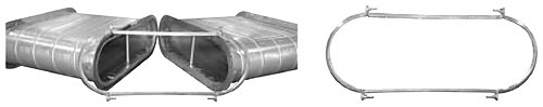
E-Z Flange with Barrel Clamp
The E-Z flange with barrel clamp can be factory installed or shipped loose for field installation. A set consists of two E-Z flanges and one barrel clamp. For field installation the installer attaches the E-Z flange to the pipe and fittings. Next the installer applies the gasket to one flange, mates the two flanges together and attaches the barrel clamp. Sheet Metal Connectors, Inc. also installs E-Z flanges. Flanges are fastened and internally sealed on both ends of spiral pipe and fittings.
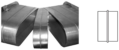
 Standard Spiral Pipe Connector
Pipe to Pipe connections are made by using a fitting size coupling that slips inside the mating pipe sections, as shown below. A stop bead runs around the middle of the coupling to center the coupling in the connection. Secure the connection by installing sheet metal screws through the outer shell of the duct, 1/2 inch from the stop bead.
Legend
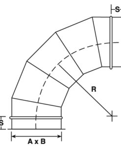
FOD – Flat Oval Duct FOE – Elbow H – Height
FOSET – Offset FOT – Tee Z – Dimension of Offset
FOS – Coupling FOL – Lateral V – Body Length
FON – End Cap FOC – Cross L – Reducer Length
FOTREC – Oval to Rectangular FOST – Saddle R – Radius
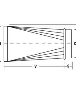
FOR – Reducer FOY – WYE Fitting S – Slip (2”)
Dimension
The “A” dimension is what you see in the plain view.
The “B” or second dimension is the hidden dimension.
Example:
A 24 x 12 FOE-90-5 is a “Hard Bend” or “Long Way” flat oval 90° elbow
A 12 x 24 FOE-90-5 is an “Easy Bend” or “Short Way” flat oval 90° elbow
When dimensions C x D, and/or E x F, and/or G x H are shown, the first dimension is the plan dimension. If a fitting end is round, use only one dimension.
Conical fittings taper only on plan side.
Vane Chart
For mitered elbows and tees use the following chart if vanes are required.
Ordering
Specify type of fitting and list the following dimensions:
Elbow – A x B Tees – (A x B) x (C x D) x (E x F) x (V)
Laterals – (A x B) x (C x D) x (E x F) x (V) Crosses – (A xB) x (C x D) x (E x F) x (G x H) x (V)
Reducers – (A x B) x (C x D) x (V) x (Z) Offsets – (A x B) x (C x D) x (V) x (Z)
The drawings shown on the following pages are illustrative of the types of fittings manufactured. SMC does not recommend deviation from these drawings.
 Note: SMACNA Testing and Research Institute verified that Sheet Metal Connectors, Inc. shop standards comply with the 1995-2nd edition of the SMACNA HVAC Duct Construction Standards.